Mathematical representation
This part represents the optimization problem formulation of the example QSE_Adequacy that is built up from basic-models_library.yml library. The referenced library includes additional models that are not used in the example and are therefore not included in the optimization problem formulation.
Glossary of Mathematical Symbols
General notation
| Symbol | Description |
|---|---|
| \(L\) | Set of transmission links (edges of the power system graph) |
| \(B\) | Set of buses, ordered set |
| \(G_b\) | Set of generators installed at bus \(b\) |
| \(L_b^+\) | Set of links for which \(b\) is the upstream vertex |
| \(L_b^-\) | Set of links for which \(b\) is the downstream vertex |
Decision Variables
| Symbol | Description | Unit |
|---|---|---|
| \(F_l\) | Net power flow through link \(l\) | MW |
| \(F_l^+\) | Power flow through link \(l\), from upstream to downstream | MW |
| \(F_l^-\) | Power flow through link \(l\), from downstream to upstream | MW |
| \(P_g\) | Power output from generator \(g\) | MW |
| \(U_b\) | Unsupplied power at bus \(b\) (in nominal state) | MW |
| \(S_b\) | Spilled power at bus \(b\) (in nominal state) | MW |
Parameters
| Symbol | Description | Unit |
|---|---|---|
| \(\overline{C_l^+}\) | Maximum transmission capacity (upstream to downstream) | MW |
| \(\overline{C_l^-}\) | Maximum transmission capacity (downstream to upstream) | MW |
| \(\underline{P}_g\) | Minimum power output from generator \(g\) | MW |
| \(\overline{P}_g\) | Maximum power output from generator \(g\) | MW |
| \(\chi_g\) | Output cost from generator \(g\) | €/MWh |
| \(\delta_b^+\) | Normative unsupplied energy cost at bus \(b\) (value of lost load) | €/MWh |
| \(\delta_b^-\) | Normative spilled energy cost at bus \(b\) (value of wasted energy) | €/MWh |
| \(D_b\) | Net power demand at bus \(b\) | MW |
Optimization Problem
The objective function to minimize the total dispatch cost for the three-bus system is:
where \(\Omega_{\text{dispatch}}\) is composed of the following cost components:
Objective function for each component
Thermal Generation Cost
For the generators in the system:
Unsupplied Energy Cost
For the three buses in the system:
where \(U_b\) represents unsupplied energy at bus \(b\).
Spillage Cost
For the three buses in the system:
where \(S_b\) represents spilled energy at bus \(b\).
Balance Constraints
First Kirchhoff's Law (Power Balance):
Flow Capacity Constraints
Flow Definition Constraint:
Thermal Units
Power Output Constraints
Power output is bounded by must-run commitments and power availability:
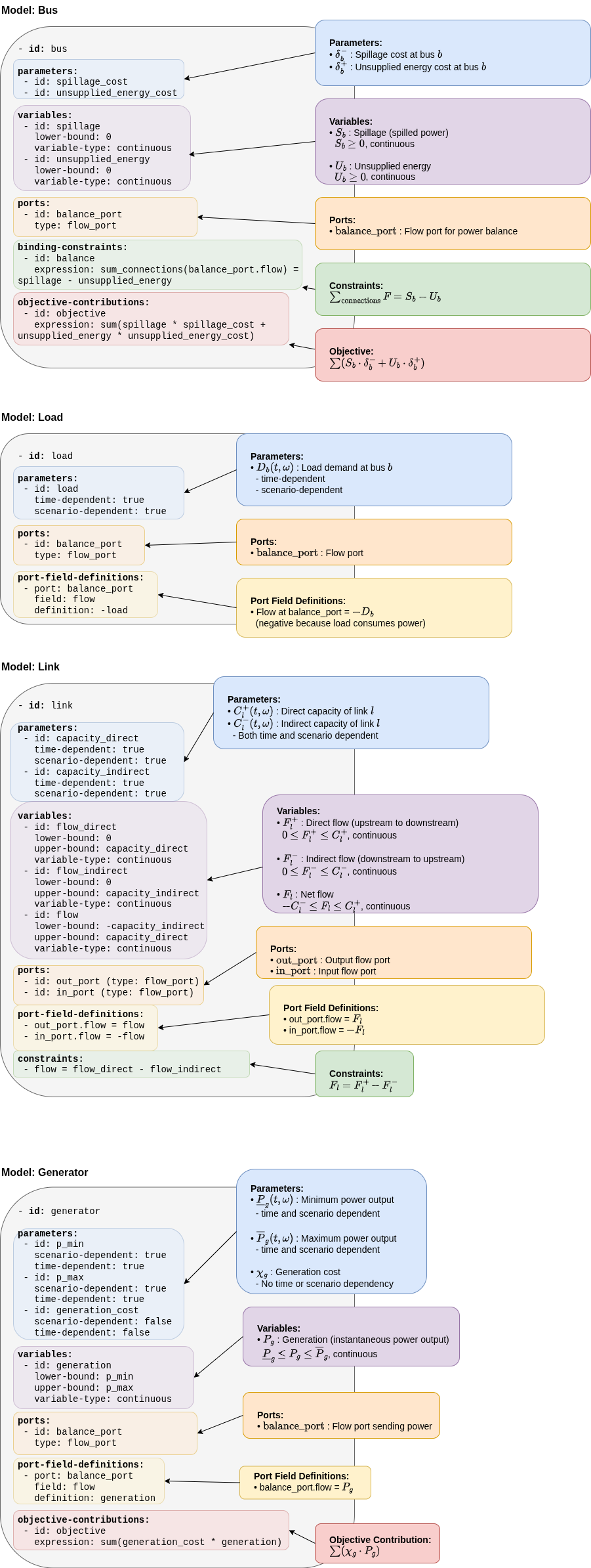
GEMS Representation and Library File
This section shows how mathematical model is implemented for every power system element that figures in optimization problem. File in which models are defined is called library file, in this case basic_models_library.yml library.
Summary
This mathematical description serves as the formal reference for the optimization problem, while the GEMS library provides its implementation layer within the GEMS framework. In other words:
-
the mathematical model defines what problem is being solved
-
the GEMS library defines how this problem is represented and can be assembled in the optimization graph
Together, the models library and the system configuration, with input data, fully reproduce the optimization problem described in the mathematical formulation.
Note that this example is configured with a single time step. As a result, parameter attributes related to time and scenario dependency are overridden in the system configuration.